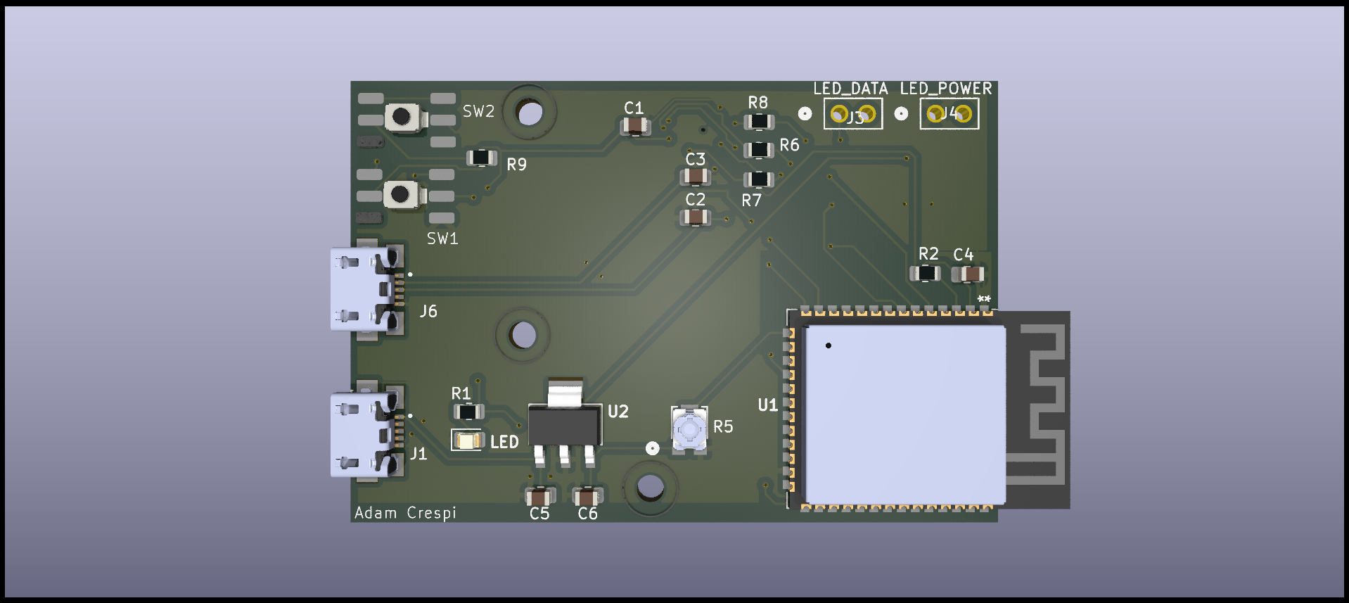
The Neural Network-Based Reactive Lighting System is an intelligent lighting solution designed to respond to verbal commands. Using an ESP32 S3 microcontroller with FreeRTOS, the system enables concurrent audio processing and LED control. A neural network trained in TensorFlow Lite interprets verbal commands to dynamically adjust lighting settings. To optimize the system's compactness, a custom PCB was designed, integrating the ESP32 S3, an I2S microphone, and supporting components.
Project Goals
- Learn PCB design with KiCad and create a PCB with an embedded MCU
- Apply digital signal processing techniques to address practical, real-world challenges
- Gain experience with Edge AI and the challenges of resource constrained machine learning
- Develop proficiency in FreeRTOS for real-time operating systems
PCB Design
The PCB design for the system brings together all the essential components in a compact and functional layout. Using KiCad, the design was created to fit the ESP32 S3 microcontroller, MEMS I2S microphone, power regulation circuits, and other supporting parts. The goal was to ensure the design was simple, reliable, and efficient, with clean connections and proper spacing to avoid signal issues. Power is provided via a micro USB port with another micro USB port for flashing the ESP.
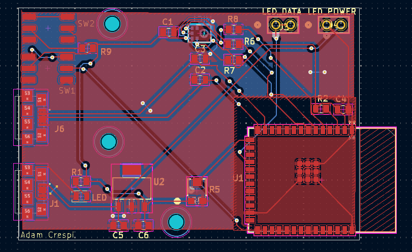
Figure 1: PCB Layout
Key Components
The PCB design integrates the following critical components:
- ESP32 S3 Microcontroller: Acts as the main processor, handling neural network inference, audio signal processing, and LED control with its dual-core architecture and advanced AI capabilities.
- MEMS I2S Microphone (SPH0645LM4H-B): Captures high-fidelity audio input for verbal command recognition, offering digital output directly compatible with the ESP32's I2S interface.
- LM3940 Voltage Regulator: Provides a stable 3.3V supply for the ESP32 and other onboard components, ensuring consistent operation under varying power conditions.
- Ceramic Capacitors (CL21A106KOQNNNE): Used for power line filtering and signal decoupling, reducing noise and improving stability.
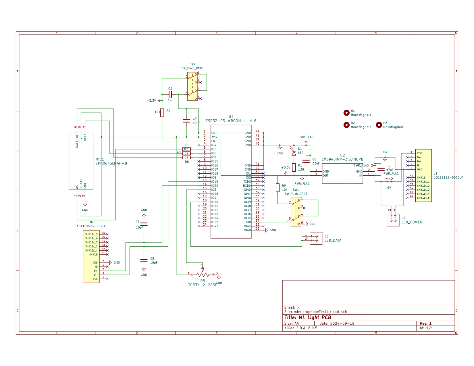
Figure 2: Schematic
PCB Assembly
Components were ordered through Digikey and boards through JLCPCB. A stencil was also used for ease of assembly in applying the solder paste. The board was assembled using an assisted pick and place machine courtesy of the UBC Engineering Physics project lab.
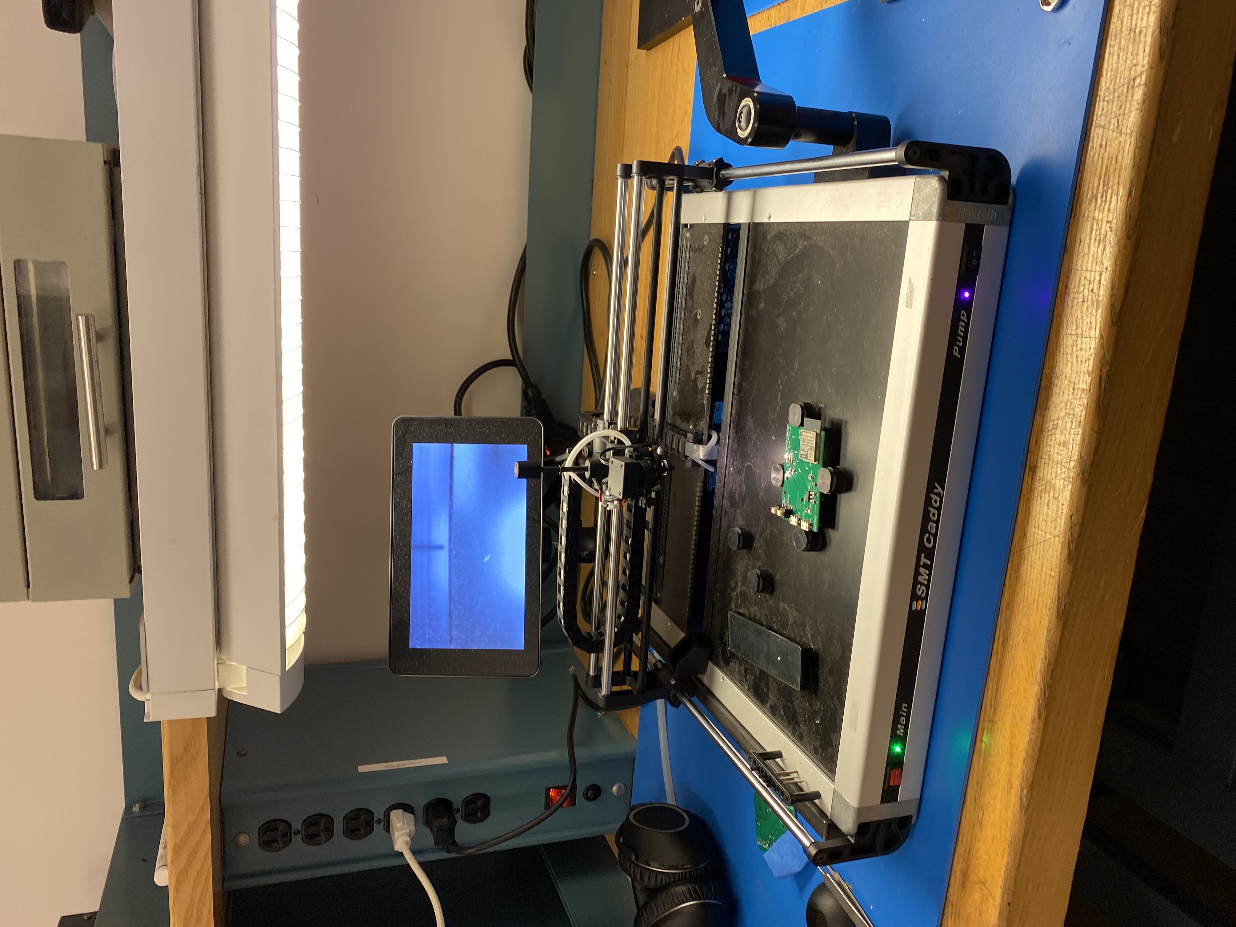
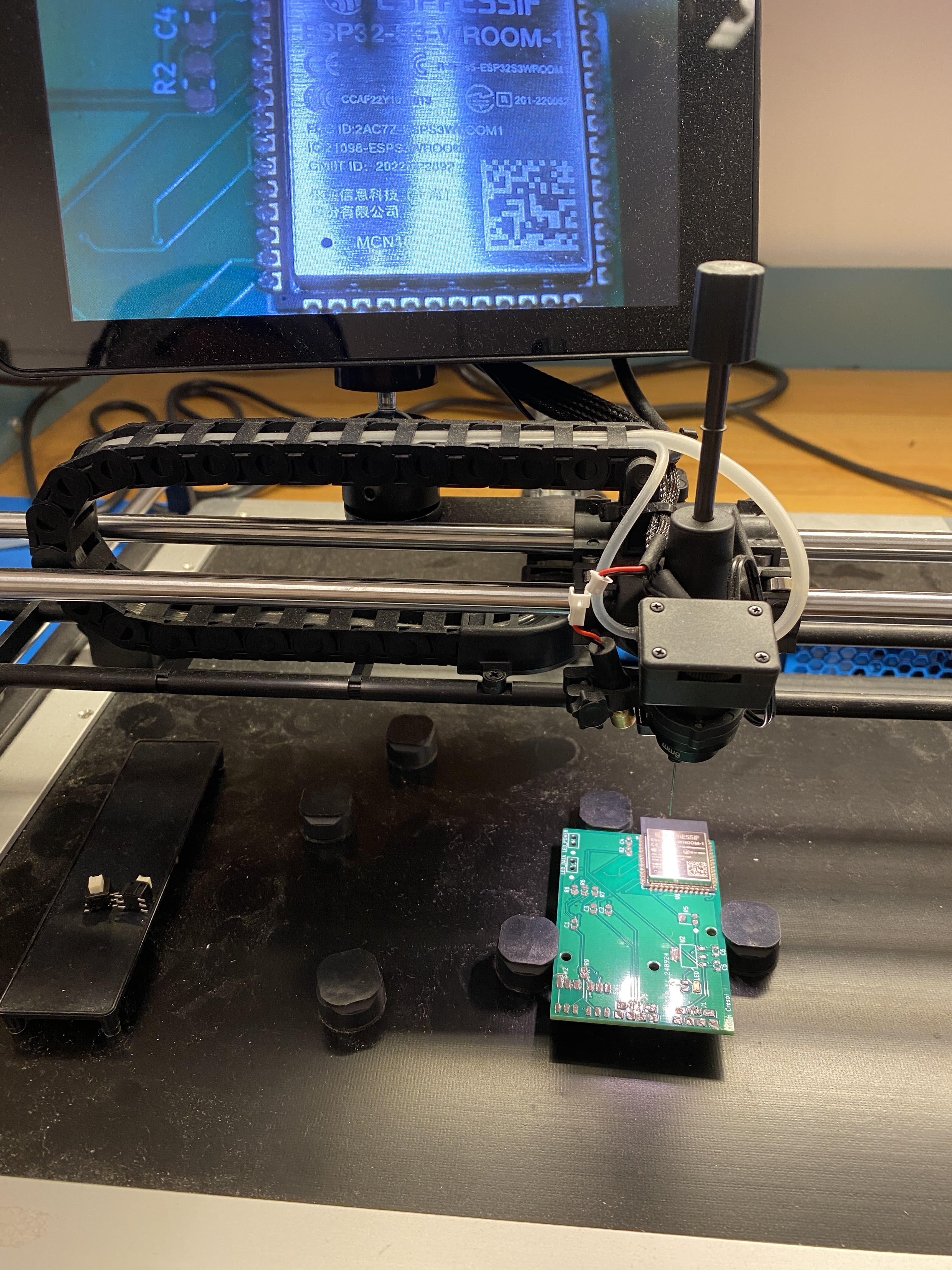
Figure 3: Assisted Pick and Place
After assembly, the board was reflowed in a reflow oven and design verification was performed. I did continuity testing across components and traces, specifically focusing on some of the resistors I accidentally bought in 0400 size.
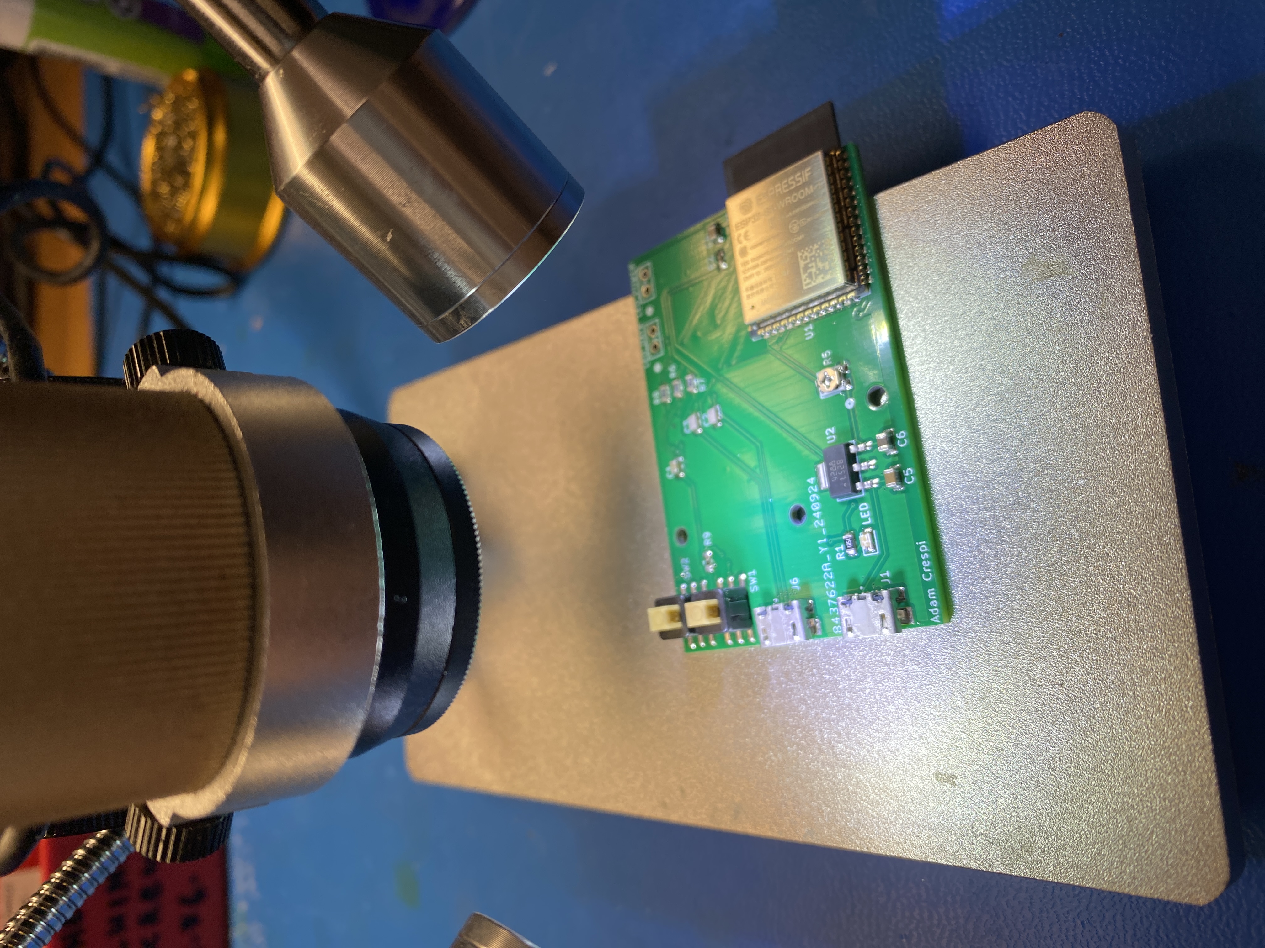
Figure 4: Design Verification
After assembly, for my first test an issue arose with the switches due to an incorrect footprint in the PCB design. This error caused the switches to short the power supply, resulting in the PCB getting hot. To resolve the problem, a quick fix was implemented by manually soldering a switch to the side of the board.
After all this, the PCB was fully functional.
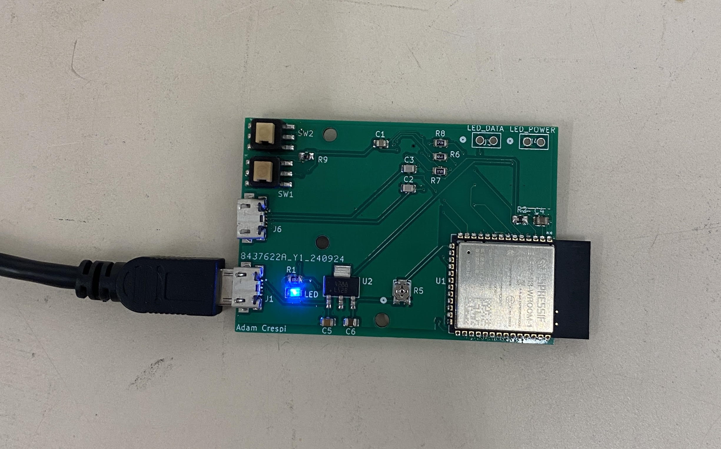
Figure 5: Fully functional PCB on second test
The Software
The software integrates audio processing, signal analysis, and machine learning. Using the ESP32 S3 microcontroller with FreeRTOS, the system handles audio data from an I2S MEMS microphone. Key steps include framing, windowing, and Fourier Transform to extract features, which are then processed by a TensorFlow Lite neural network to adjust LED patterns in real time.
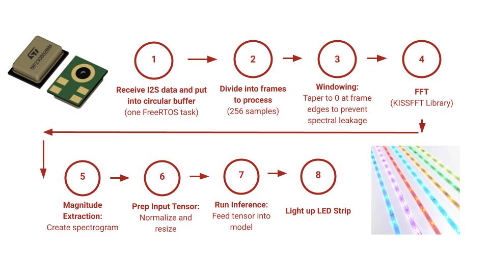
Figure 6: Software Diagram
FreeRTOS
The system relies on FreeRTOS to handle the simultaneous tasks required for real-time audio processing. One FreeRTOS task manages the reception of I2S data from the MEMS microphone, efficiently storing the audio data into a circular buffer. This ensures smooth data flow and prevents any loss of audio frames during processing. The second core can then focus on the digital signal processing and inference. A circular buffer is used to prevent race conditions from concurrent actions to the same memory. For my implementation, I simply assigned one of the ESP32's dual cores to each task.
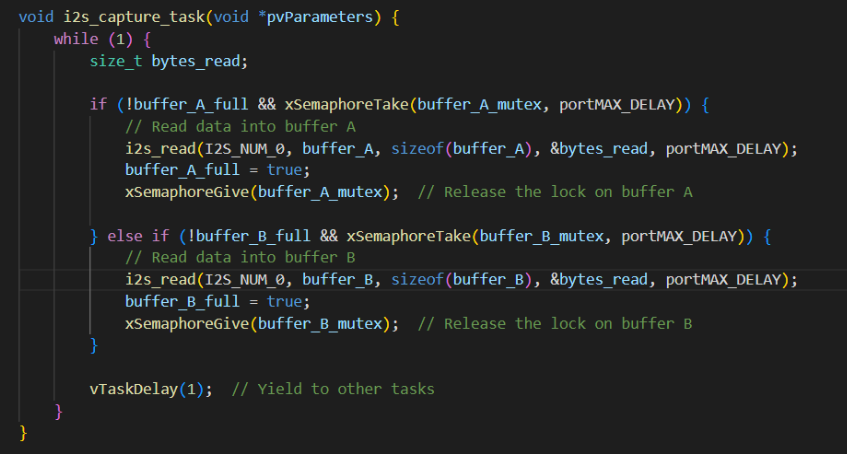
Figure 7: FreeRTOS I2S Capture Task
After finishing this project, I also learned that I2S for the ESP32 S3 has Direct Memory Access (DMA). This means that pushing the data from the MEMS microphone into the circular buffer doesn't require much CPU compute, and a task just for storing the data is not really necessary. If I were to redo this, I could break up the digital signal processing into tasks to be split across cores. However, I would have to be more careful with race conditions.
Signal Processing
The signal processing pipeline involves several key steps to transform raw audio data into a spectrogram suitable for neural network inference. We will take a sine wave input signal to see this process.
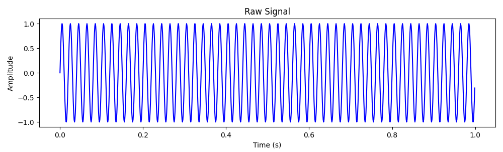
Figure 8: Raw Sine Wave Input
Sampling
Sampling involves capturing raw audio data at discrete time intervals to convert the continuous signal into digital form. In this case, a sine wave is sampled at regular intervals to create a digital representation.
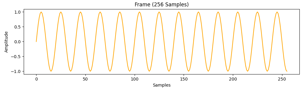
Figure 9: Sampled Sine Wave
Windowing
After sampling, the signal is divided into smaller frames of fixed length. These sampled frames also overlap by 50% to ensure no information is lost. I chose frames of 256 samples for compatibility with the neural network. To reduce spectral leakage, each frame is multiplied by a window function (e.g., Hann window), which tapers the signal values at the edges to zero. This ensures that transitions between frames are smooth and minimizes distortion in the frequency domain.
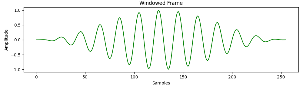
Figure 10: Windowed Sine Wave
FFT
Once the windowing is applied, the Fast Fourier Transform (FFT) is performed on each frame to transform the signal from the time domain to the frequency domain. The FFT breaks down the signal into its constituent frequencies, providing insight into the amplitude of each frequency component within the frame.
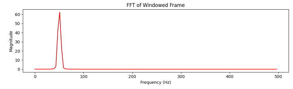
Figure 11: Sine Wave in the Frequency Domain
Spectrogram
Finally, the magnitude of the FFT results is extracted to generate a spectrogram. The spectrogram is a visual representation of how the signal's frequency content changes over time, displayed as a 2D image where the x-axis represents time, the y-axis represents frequency, and the color intensity indicates amplitude. This spectrogram serves as the input for the neural network to make inferences.
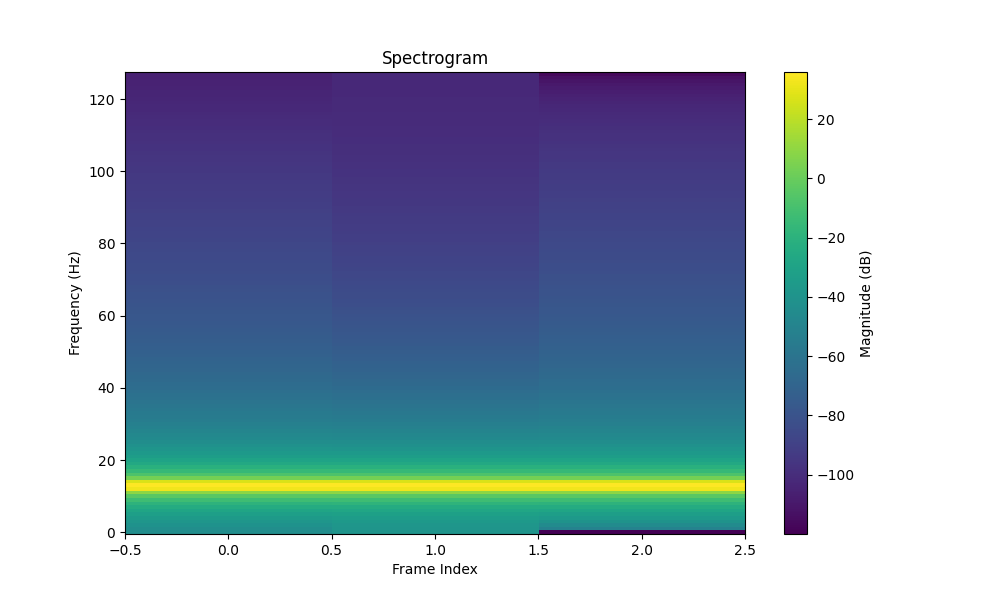
Figure 12: Final Spectrogram
Inference
The inference phase involves utilizing a neural network to analyze spectrograms and classify them into one of eight predefined categories based on spoken words.
Prepping Input Tensor
Before the spectrogram can be fed into the neural network, it needs to be preprocessed into a compatible input tensor format. The spectrogram is resized to 128×128 to match the input layer dimensions of the model. Additionally, normalization is applied to scale the data values between 0 and 1, ensuring consistency across inputs and improving the model's convergence during training.
The Model Itself
The model was trained using Google Colab on a set of spectrograms from Google's mini Speech Commands dataset. Optimization techniques like pruning and quantization were applied to reduce the model's size and adapt it for deployment onto the ESP32 S3. I managed to compress my final model down to 5 MB.
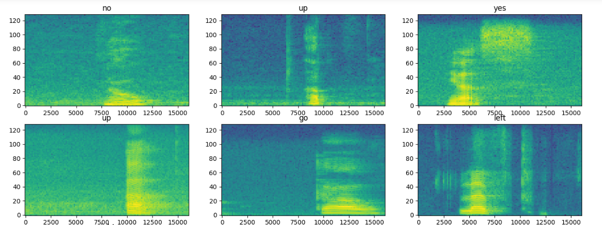
Figure 13: Spectrograms of Words
Conclusion
This project successfully combined AI, signal processing, and embedded systems to create a responsive solution. Using the ESP32 S3 and a custom PCB, the project achieved real-time performance and met its goals. See the final product below, responding to my stop command.
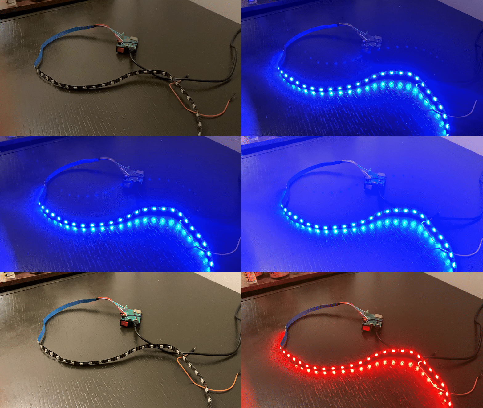
Figure 14: Final Product